


Given the wide scope of measurement ranges offered, this machine range is designed to adapt to current and future manufacturing demands.
From 40 to 180 mm in diameter, and 300 to 1250 mm in length, the modular range of the Techno series can provide you with the most suitable machine for your production.
 Politica de securitate (editeaza cu modulul Reasigurare pentru clienti)
 Politica de livrare (editeaza cu modulul Reasigurare pentru clienti)
 Politica de returnare (editeaza cu modulul Reasigurare pentru clienti)

Detailed images capture even minute features.
Each part produced by the CNC lathe can be measured within the production environment.
Batch changing is fast and efcient.
A single system can operate next to multiple machining centers, involving more than one operator.

Reduction in machine downtime thanks to immediate inspection without the need to leave the wokstation.
Significant reduction in rejects, implementing the preventive actions indicated by the measurement trend graphs.
It is possible to set the interface between MTL and the workstation to automatically correct tool parameters. This function eliminates human error and speeds up tool parameter settings. Each part produced is ready to
be delivered.
Operators are more independent during inspection and tool ofsets can be adjusted before parts become out of tolerance in order to reduce the amount of rejects produced.
Software
The software has been developed by VICIVISION to make the complex computing power user-friendly. For this reason the interface is divided into two macro environments:
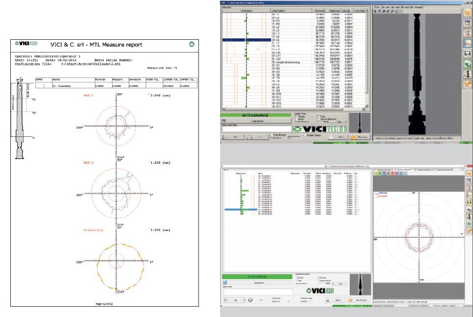
Production environment: designed for use by various operators with diverse computer knowledge. This environment is extremely practical and intuitive with a bar chart or semaphore graphic display which gives the operator an immediate good/reject result.
In this environment the operator can load a “piece program”, carry out all measurements with a single click, print out a report complete with graphs and check each single measurement in order to make corrections and save the data for statistical purposes. The operator carrying out the measurements in production will see the image of the piece displayed on the monitor and will have the same practical sensation as the profile projector.
In addition, with the graphics it is possible to highlight the non-conforming measurements and the operator can immediately check the level of piece cleaning, if traces are present or other irregularities that may have conditioned the measurement.
Programming environment: developed to express all the machine’s computing potential and provides the possibility of intuitive programming, from simple static measurements (diameters, lengths…) to more complex ones.
Each measurement obtained can be included or excluded in the measurement report, in the statistics or on the production panel.
Programming is carried out directly on the real image of the piece. This characteristic gives a clear view of the conditions of the item to be measured (size of the detail, quality of finishing and cleaning, fixing conditions….).
The image of the piece is displayed vertically, as it is in the machine, with immediate orientation also of small and symmetrical pieces.
The program environment is also available “off-line” so that programming can be done from the comfort of the office, maintaining the same programming accuracy and conditions.
List of standard measures included in the MTL application:
Model
M304 Techno - Technical Data |
|
|
Model |
M304 Techno |
|
Max. measurable piece |
300x40 mm |
|
Max. piece to be loaded |
315x120 mm |
|
Max. weight to be loaded |
10 kg |
|
Measurement accuracy on diameter (average diam.) |
(1.5+D[mm] / 100) μm* |
|
Measurement accuracy on length |
(4+L[mm] / 100) μm* |
|
Measurement repeatability on diameter (average diam.) |
0,3 μm* |
|
Measurement repeatability on length |
1,2 μm* |
|
Vertical scanning speed |
100 mm/s |
|
Rotational scanning speed |
1080 °/s ** |
|
Machine’s weight |
160 Kg |
|
Power supply |
230V – 50/60 Hz |
|
Dimensions LxWxH |
595X780X950 mm |
|
It requires supporting bench made of welded steel or granite top (suggested dimensions – VV5.14) LxWxH |
1400x850x710 mm |

Given the wide scope of measurement ranges offered, this machine range is designed to adapt to current and future manufacturing demands.
From 40 to 180 mm in diameter, and 300 to 1250 mm in length, the modular range of the Techno series can provide you with the most suitable machine for your production.